Micronova Pellet Stove LCD Reverse-Engineering
While trying to find out a way to communicate with my pellet stove I decided to have a look at the LCD communication and maybe learn something new and have fun. It is a segment LCD and maybe you find this useful, especially when designing your own control panel or reusing the LCD from a broken panel.
Control panel/LCD display
I decided to disassemble the control panel (with buttons and LCD on the top of the stove). That was easy. Then I followed the PCB connections and figured out the connector pinout. I used a Brymen BM257s multimeter with audible continuity test for this (very helpful thing to have). I did some logging with Saleae logic analyser. At first I thought it communicates with the LCD by I2C but there was no start / stop sequence. By looking at the timing of data and clock lines I figured out it’s SPI with 8 data bits, MSB first, CPOL 1 (clock high when inactive), CPHA 1 (data valid on clock trailing edge). There is a HC42 decoder on the board. By watching A, B and C lines it sets one of the 8 outputs to LOW while putting others to HIGH. When it’s encoding maximum number 7 (A=HIGH B=HIGH C=HIGH) it sets LOW to the line going to the LCD. So it’s a chip enable pin for LCD. During that time the data from D1 and the clock from D2 pin is consumed by the LCD. It sends some starting bit sequence, then one bit per LCD segment (1 to enable the segment, 0 to disable it). Total 45 bytes (360 segment bits).
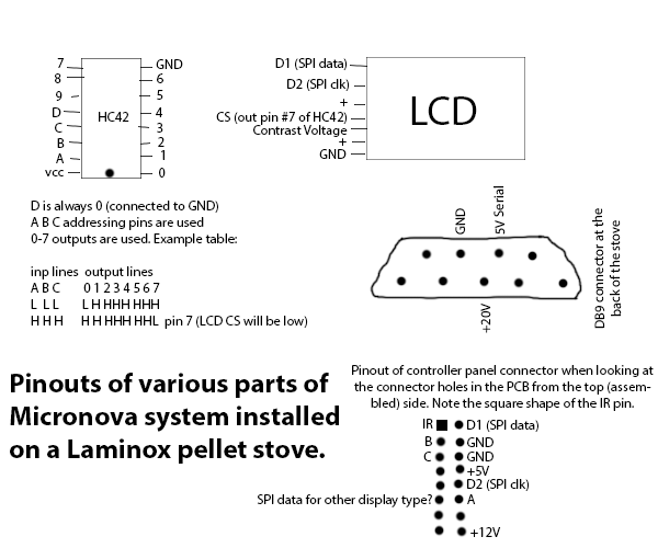
Various pinouts
To simulate sending data to LCD I made an Arduino sketch. Here are the segment indices – the last digit specifies bit position inside a byte, digits before represent in which byte that bit is located. To test the sketch just connect D1 pin to pin 11 onthe Arduino, D2 to pin 13 onthe Arduino, ABC together to 2 pin on the Arduino, connect 5V to + and GND to any of those two GND pins. By default the sketch will display some text and number characters on the LCD, you can change what to display by changing WHAT_TO_TEST define to one of the TEST_* pre-defined values.
Buttons works this way: When A B C lines encode a number lower then 7, it sets LOW (0V) to one of the transistors connected to each button. That low voltage is put to the base of a PNP transistor which brings the D1 pin to LOW (0V) when a button is pressed. So the controller board in the stove knows the button encoded by A B C line status was pressed. The stove board cycles the A B C line HIGH (5V) status so that it’s 1, 2, 3….7, 1, 2, 3…. while watching the state of D1.
There is an IR receiver on the board (TSOP382). You can learn more about how IR communication works with this device here. Funny thing is that as we know (from the IR commands section of this page) Micronova didn’t use this common mark and space encoding but they are directly sending modulated data bits. So what goes out of this device is 5V for incoming bit 0 (or no signal) and 0V for incoming bit 1. There are capacitors parallel to the TSOP which is a recommended thing to filter the voltage and prevent spurious detection as the TSOP receiver is very sensitive. There is 100 ohm resistor in series to the receiver power supply. The receiver output is connected directly to IR pin.
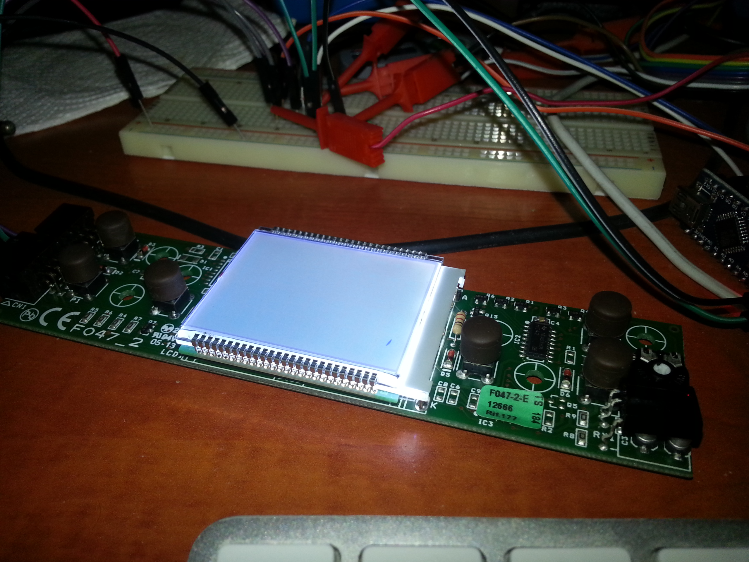
LCD test with one segment shown
[…] first I was thinking of parsing LCD segment bits and getting textual LCD data as a form of feedback. But that is quite crazy and unnecessarily […]