Controlling Micronova pellet stove motherboard – Stufe a pellet Aria Idro IR telecomando seriale
Here is how to control a pellet stove with a Micronova controller remotely either via IR commands or using the serial line.
They installed a Laminox pellet stove in our house. It is a nice thing to have over the winter. Problem is that sometimes I am outside and I want to turn on the stove remotely so that when I arrive, it will be warm inside. So I needed a way to control it remotely. By google searching pellet stove controllers I noticed that mine looks very similarly as those made by Micronova so it was clear – the controller inside my stove is some board from Micronova (i023, i050 or who knows). It is used by various stove manufacturers like Laminox, Extraflame, Evacalor, Dalzotto, Ungaro, Arcestufe, Karmek, Tecnoflam, Termoflam, Clam, Cadel, Zibro, Sicalor, Kepo, EcoTeck and many others. I noticed a DB9 connector at the back of my stove but no! It is not an RS232, there is 20V on one of the pins and I destroyed my UART interface trying to connect it to the stove (right, I should have checked the voltage levels on each pins first, lesson learned, but the interface is not expensive and I have more pieces at home anyway).
I contacted one of Micronova employees just asking if it is possible to turn on the stove via that connector or if it would be just waste of my time trying to figure out how to do it. And he replied that if I am not from one of their partner companies they can’t tell me anything. Right, thank you. I bought this stuff and it’s now mine so I want and will do what can be done with it myself! So I decided to spend some time with this.
Fist I did some research on IR remote. Later I found some helpful information about the serial communication in Italian at stufapellet.forumcommunity.net (thanks!). It was not all in one place there and not complete. As I also recently purchased a Rigol oscilloscope and had a Salea logic analyzer available so I did more work on this subject and I am finally able to describe it in more details.
IR commands

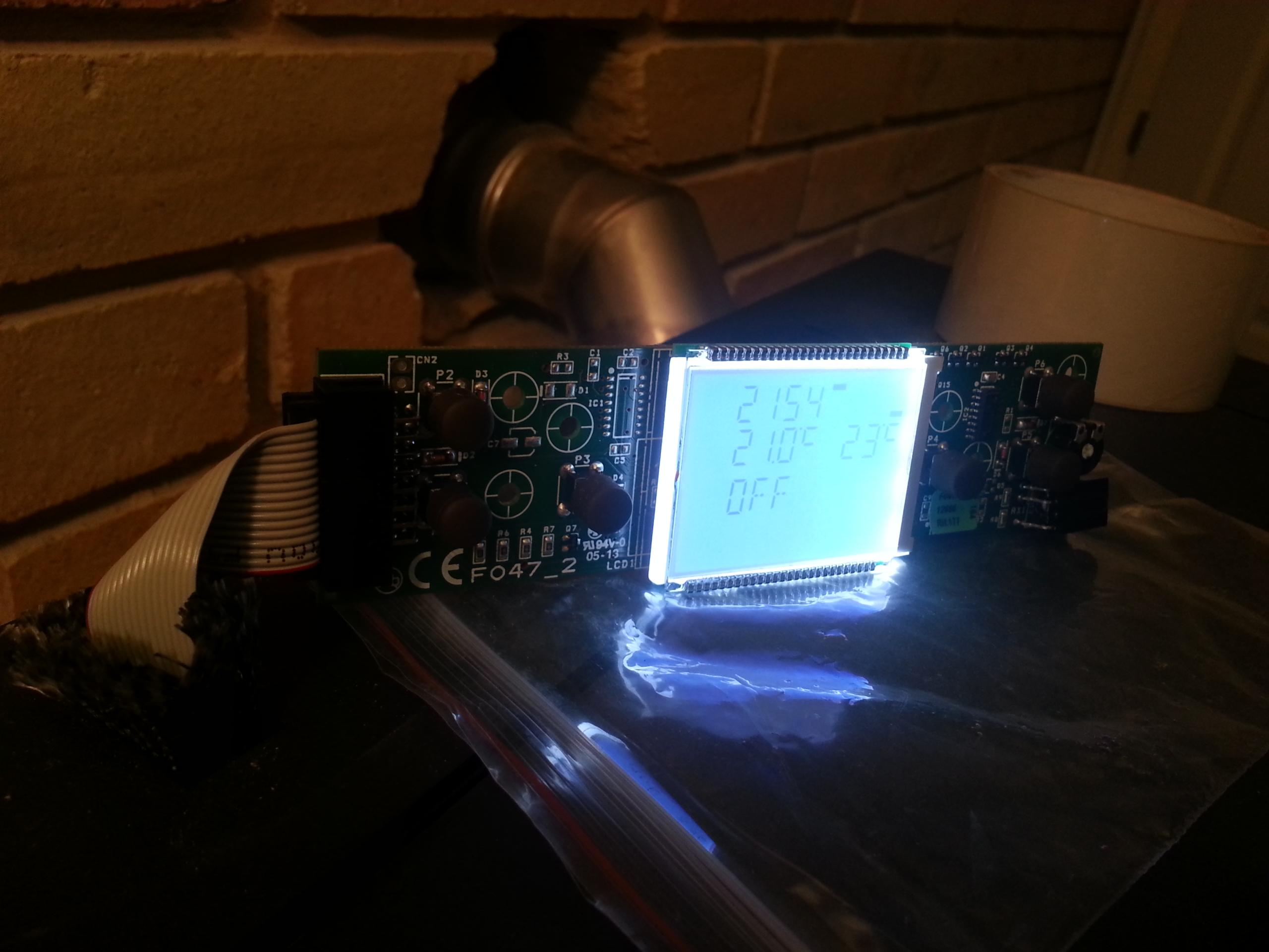
This is the original IR controller
It’s not difficult to send IR commands for this stove using an Arduino.
Here is a table of commands I created by recording the IR LED voltage with a PC line-in sound card port, then analysing the recording with Audacity (before I had a logic analyser at hand):
== Setting the power ==
r up   11111111 00011110 01010011 10101010 01110010 11000000
       0xFF     0x1E     0x53     0xAA     0x72     0xC0

r down 11111111 00011110 01010011 11101010 01111010 11000000
       0xFF     0x1E     0x53     0xEA     0x7A     0xC0

== Setting the water and air temperature ==
l up   11111111 00011110 01010011 01101010 01101010 11000000
       0xFF     0x1E     0x53     0x6A     0x6A     0xC0

l down 11111111 00011110 01010011 11001010 01111100 11000000
       0xFF     0x1E     0x53     0xCA     0x7C     0xC0

== Power up ==
power  11111111 00011110 01010011 01001010 01101100 11000000
       0xFF     0x1E     0x53     0x4A     0x6C     0xC0
38 kHz modulation seems to work fine (36 kHz may work too). I created a testing Arduino code based on Infrared library. It sends the ‘power setting down’ command every four seconds. Just connect an IR LED to GND and D3 pins (ideally with a 100 Ohm resistor in series).
Serial communication
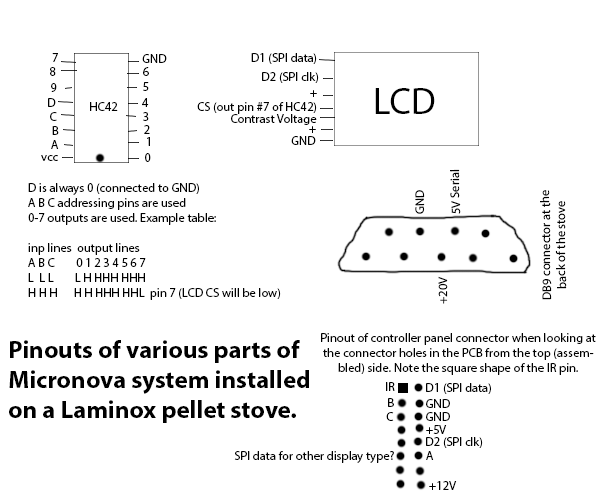
Well, first I was thinking of parsing LCD segment bits and getting textual LCD data as a form of feedback. But that is quite crazy and unnecessarily complicated. I knew there is a DB9 connector at the back of the stove and while I didn’t know the pinout I suspected that it may be connected to the SERIALE connector (CN13) on the main board. I have read some italian threads. They were mentioning there is ~20V, GND, +5V pins. Right. First – GND is not connected to stove’s metallic frame. This metallic frame is connected to protective earth but the stove has it’s own GND reference for all communication stuff. So I picked up known GND from the controller panel and measured voltages on every pin. Turned the stove off and measured resistance between GND and those pins. And here are the pinouts.
Out of curiosity, when the stove was off, I also measured resistance between IR pin on the controller panel and all pins in the DB9. And also resistance between +5 pin in the controller panel and all pins in the DB9. And guess what! There is about 500 ohm between IR pin and serial pin. Aha, so it uses almost the same path for IR as well as serial commands. Interesting. It seems that 500 ohm resistor is on the DB9 (CN13) side and there is no resistor on the IR side.
Unfortunately, as they mentioned in the forum, only one pin is used for RX and TX. UART logic levels are ~5V for logic 1 and ~0V for logic 0 (for exact ranges see 5V CMOS logic). When the stove or the PC wants to write a bit with logic value 0, it needs to pull down this serial pin (~ <1V). When it wants to send a bit 1 it can keep it at 5v (it is pulled up apparently so no need for an extra pull up resistor). In the forum they made some crazy schematics with optocuplers and transistors (here and there). :D But there was one simple schematic. I don’t have that chip nearby but it made me start experimenting. I created an arduino sketch again to just simulate me this NC7WZ07 device. You can connect TXD from CP2012 to pin 2 and on pin 3 you will get output to go on the stove’s serial line. UPDATE: you can use a diode instead of it, read on.
I created this simple schematic with just one PNP transistor and one diode. It works fine with 5V tolerant USB-to-TTL converter based on CP2102 and it doesn’t echo the sent bytes if the diode has higher forward drop, let’s say 0.7-1V. It’s a bit of trial and error but it works with SeramiNet.
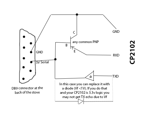
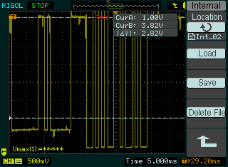
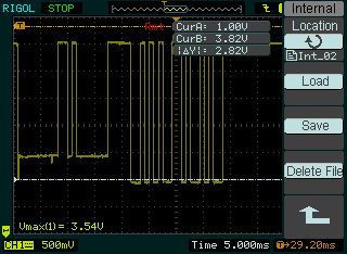
It works like this: when TXD is logic 0 it’s 0V so the diode will act almost like a wire (with Vf though) so there will be Vf (around 0.8V depending on your diode on the serial line so the 5V stove logic will pick it up as a logic 0, when TXD is logic 1 it will be on 3.3V on that side, that will be reducing stove controller’s serial voltage to 3.3+Vf max (from it’s default pulled up 5V). But because the stove is pulled up with a high resistance pullup, there will be a very tiny current flowing so it’s fine. Because there will be ~0.8V on the stove’s serial line, it won’t be picked up by 3.3V logic of RXD (higher than it’s max low level voltage), thus cancelling up the echo, yay! To illustrate here are some screens from the oscilloscope at stove’s serial line and RXD of the CP2102 for the same request and response. White line is 1V, 0V is at the bottom of the screen. At the serial line of the stove there is max 3.8V.
I intend to control the stove using Espressif ESP8266, a cheap chinese SoC with wifi and IP stack. It is 3.3v and it’s not 5V tolerant. While receiving can be done using a voltage divider (two resistors), sending is problematic. UPDATE: as Gus suggested in the comment, one diode and NPN transistor is a better way to do the half-duplex trick. Also NPN transistors are probably more common. So for my ESP8266 project I used this idea and just added one zener diode on the TX side of the ESP to protect TXD from getting voltages higher then 3.6V. Here is the schematic I use and the board made in free version of Eagle:
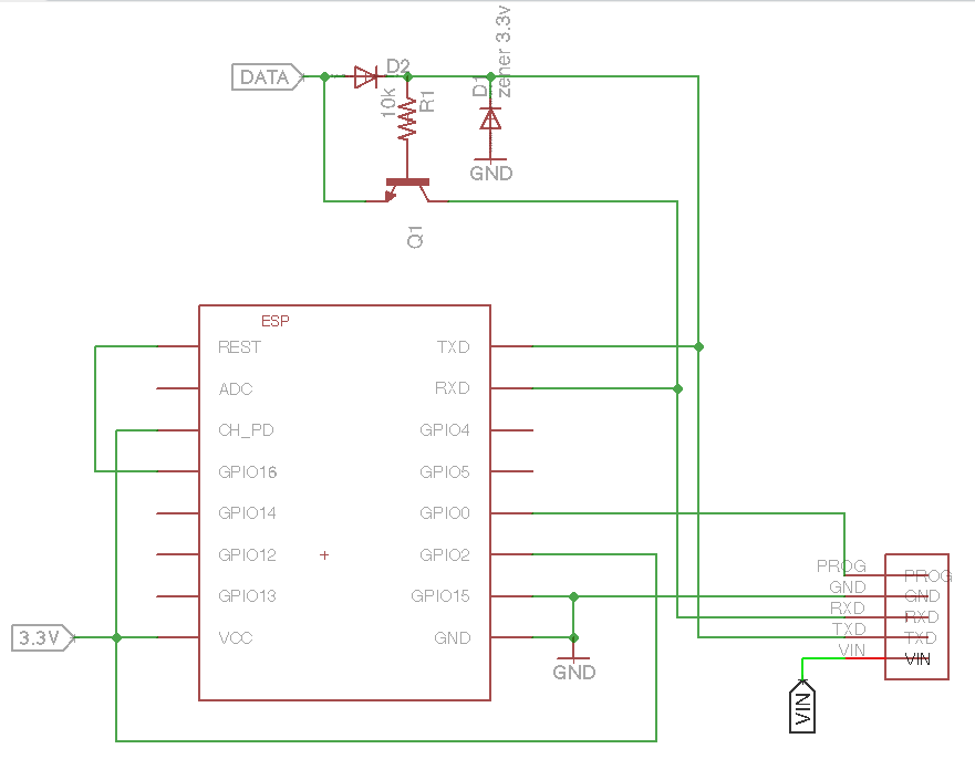
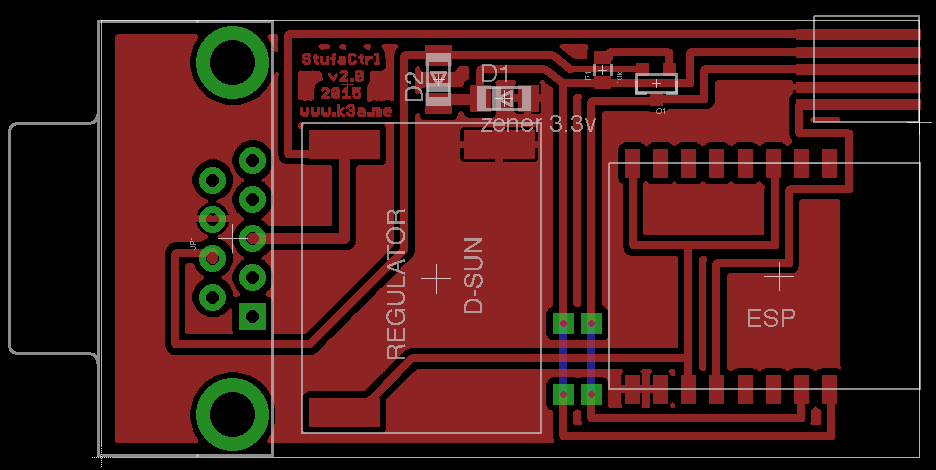
What you see as REGULATOR is a tiny switching regulator to convert 20V from DB9 connector to the 3.3V needed for the ESP8266. Don’t use LDO (linear regulator) for that purpose as the voltage difference is high and current can be ~200 mA meaning it would produce more heat than the ESP would be consuming. :D
Serial Protocol
Their protocol is called Rwms. It’s a simple binary serial protocol which works half-duplex. You are either sending or receiving.
There are two accessible memories on board. RAM and EEPROM. RAM is volatile memory which can be rewrote many times safely. EEPROM is the memory used for storing settings which are preserved after the stove is turned off. EEPROM should not be rewrote many times as writing cycles are limited (commonly 10-100k depending on the memory technology).
Connection parameters are: baud rate 1200, 8 data bits, 2 stop bits, no parity, no flow control. There are two commands – Read and Write.
Read
two bytes (TYPE+ADDR_MSB) ADDR_LSB
– where TYPE is 0x00 for reading from RAM and 0x20 for reading from EEPROM
– ADDR_MSB optionally the most significant byte part if the address is longer than 8 bits (you can put 0 there/ignore it)
– ADDR_LSB least significant byte of address (item index) to write to
– ADDRESS is just a memory position index, starting from 0x00 to 0xFF
response from the stove are two bytes CHECKSUM VALUE
– CHECKSUM is (TYPE+ADDR_MSB+ADDR_LSB+VALUE) & 0xFF
– VALUE is the returned value (it can be 255 decimal max)
To read a temperature (looks like ambient temperature for my board) you would send 0x00 0x01. It seems that indices may be different for different board so you have to experiment. Index 0x67 was hour and 0x68 minute while for Italian forum people it was 0x65 for hours and 0x66 for minutes.
Write
four bytes (0x80+TYPE+ADDR_MSB) ADDR_LSB VALUE CHECKSUM
– TYPE again 0x00 for writing to RAM, 0x20 for writing to EEPROM
– ADDR_MSB optionally the most significant byte part if the address is longer than 8 bits (you can put 0 there/ignore it)
– ADDR_LSB least significant byte of address (item index) to write to
– VALUE value to write (so it can be 255 decimal max)
– CHECKSUM is ((0x80+TYPE+ADDR_MSB)+ADDR_LSB+VALUE) & 0xFF
stove responds with two bytes: ADDR_LSB VALUE
– repeating the values sent there
Known Variables
These are variables mentioned on the Italian forums. These addresses seem to be different for different boards though so it’s more just for a reference…
== RAM ==
0x00 internal timer of the program (ranging from 0-255 continuously)
0x01 temperature multiplied by 2
0x0D pellet loading in use (formula !!)
0x21 power state (0-stove off, 1-stove start)
0x37 speed 'fan fumes using (formula !!)
0x5A smoke temperature
0x63 seconds current
0x64 DOW (day of week)
0x65 current time
0x66 minutes current
0x67 date current
0x68 current month
0x69 current year
0x73 intake air temperature
0x7D copy of the set temperature from EEPROM

== EEPROM ==
0x08 FAN SMOKE IN POWER 5
0x7D set temperature
You can turn on the stove by writing 1 to 0x21 in RAM so the bytes to send would be 0x80 0x21 0x01 0xA2. The stove responds with 0xA2 0x01.
UPADTE: Another parameter table is mentioned in this thread.
UPDATE2: Parameters for my hydro pellet stove (all RAM):
0x00 some internal timer, constantly changed over time
0x01 ambient temperature (multiplied by 2)
0x02 ??? (started around C, maxed around 95)
0x03 water temperature
0x19 stove power control? Must be set in EEPROM I guess
0x21 state (0-off, 1-starting, 2-load pellet, 3-flame light, 4-work, 5-cleaning, 6-, 7-cleaning final)
0x34 current stove power
0x3B water temperature (copy of 0x03)
0x3C water pressure (multiplied by 10)
0x5A smoke/fumi temperature (started around 24 deg C, maxed to around 126 deg C)
0x65 current second
0x66 current day of week?
0x67 current hour
0x68 current minute
0x69 current day
0x6A current month
0x6B year since 2000
0x6D stove water temp control
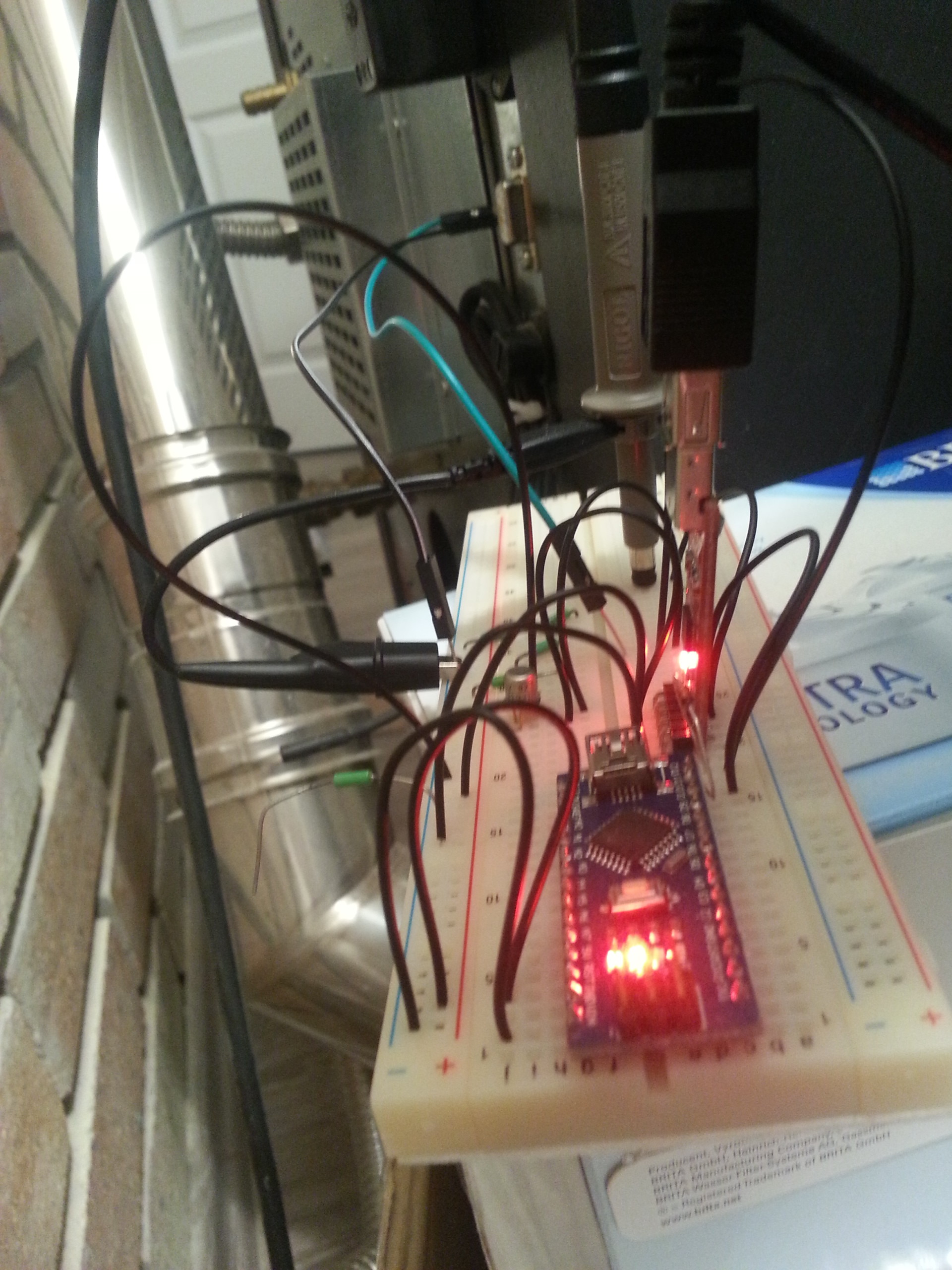
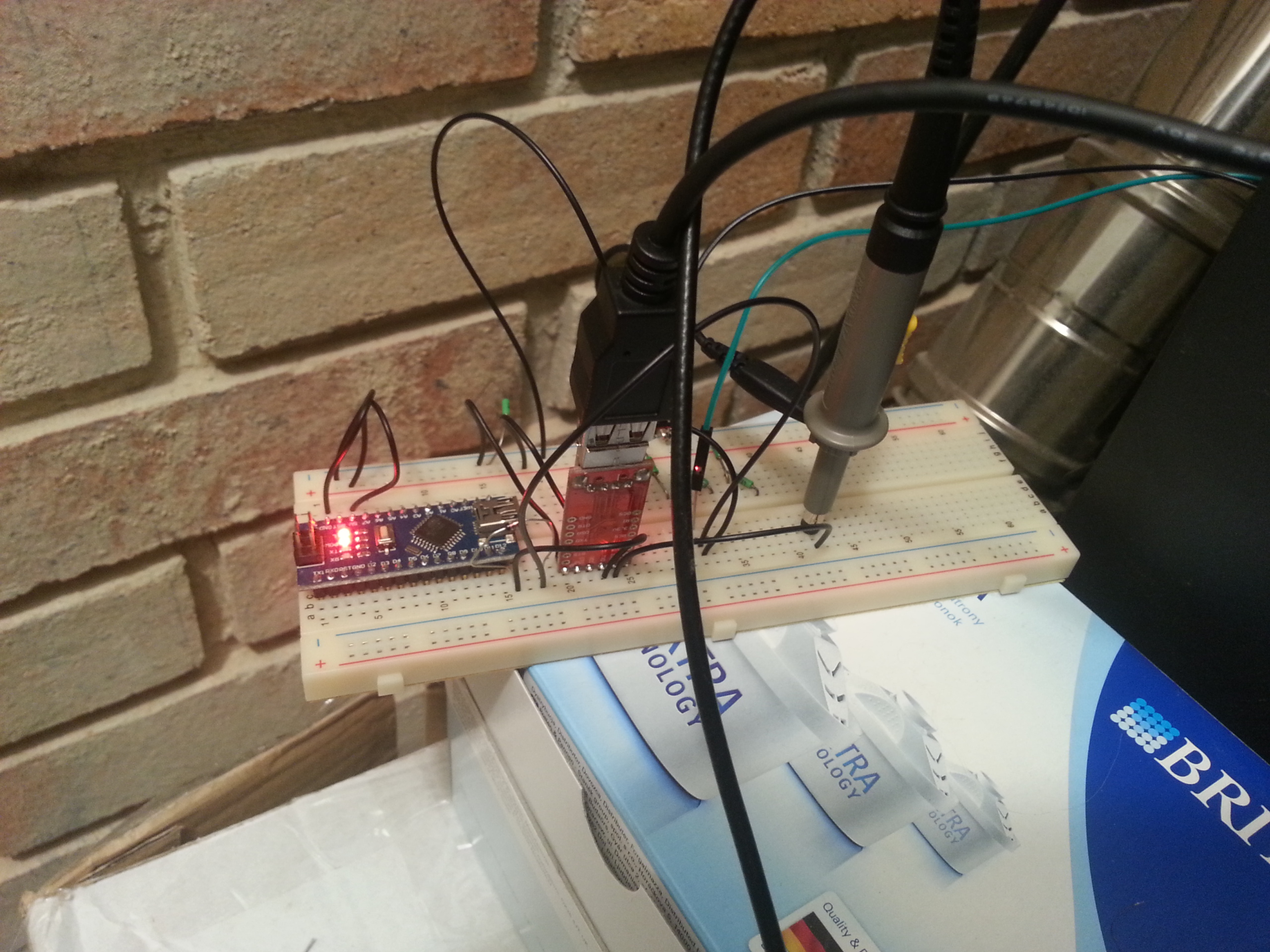
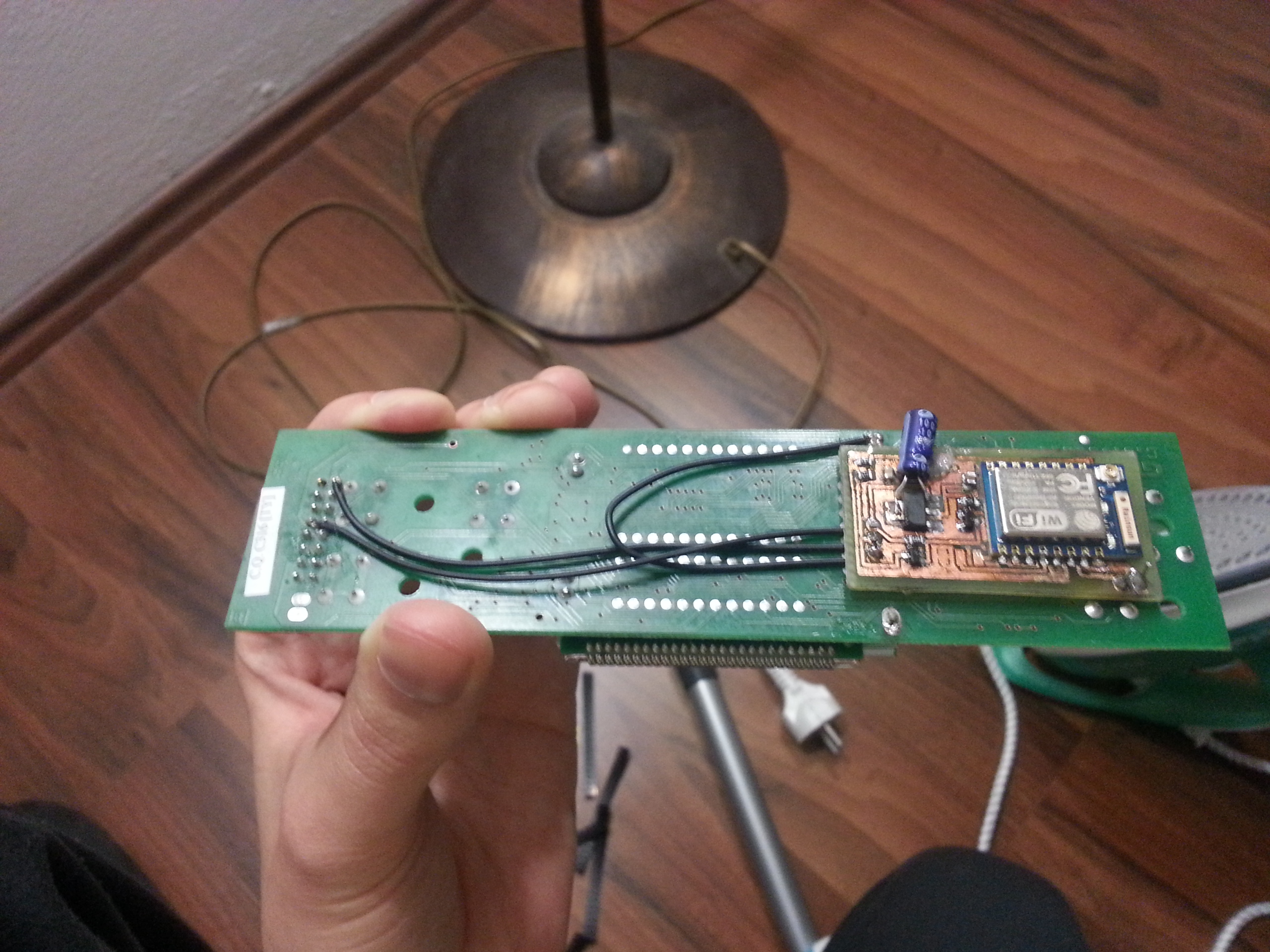
My first custom control board (telecontrollo)
This was the first board I made (left). I decided to power it directly from the stove’s control panel. It was hidden in the stove. Worked fine, but one night I realised it may not be ok to stress the stove’s 5V regulator so much. ESP8266 can draw ~200 mA which is not that small. So I made a new board with switching regulator and DB9 connector to be connected at the back of the stove as an accessory.

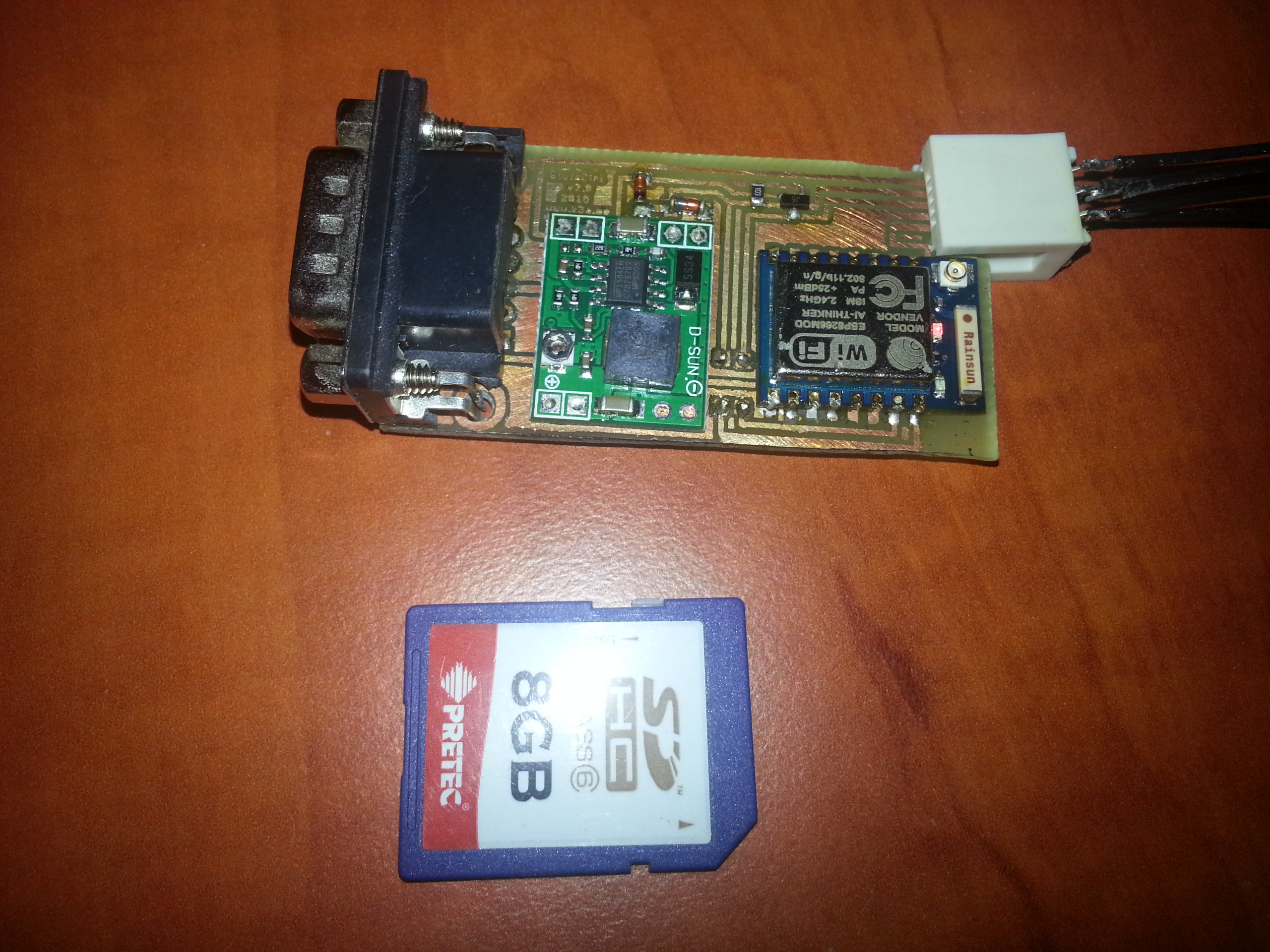
My second control board
This is the final board I made. It looks like an accessory and has the board edge connector for programming the ESP8266. Currently I use my own firmware written in C but I am actually working on a scriptable firmware which I may opensource at some point. I didn’t want to use NodeMCU or Arduino for ESP because NodeMCU is unnecessarily big and consumes a lot of memory and both can’t be updated too easily remotely. But both are cool projects so you can definitely consider one of them if you don’t plan more projects and don’t need rapid updates over wifi.
Micronova stuff
Micronova have some “Serial interface”. It probably has an Atmel microprocessor inside which just does the half-duplex trick. And there will be some RS232 transceiver or USBtoUART chip. :)
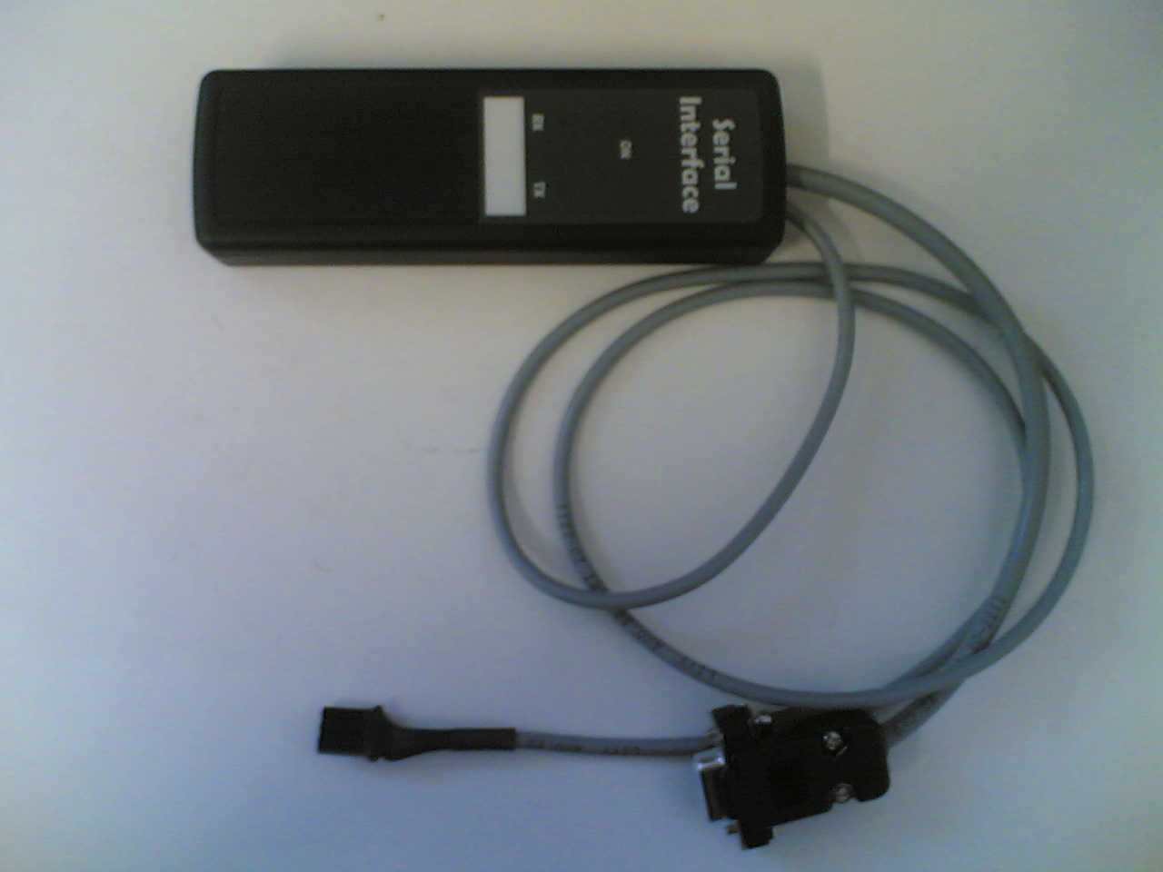
Some crappy “serial interface” gadget I don’t own
They have a proprietary software SeramiNet. It can be used for reading RAM/EEPROM parameters. It has also a console allowing you to write values. There is also a tool for flashing firmware but I am not sure if it uses the same serial interface or the JTAG pins on the board. If you ever wanted to write a firmware though, you would have to get some .enc, .hex or .ben file from Micronova and I am almost sure they won’t give you one unless you are a partner company. :P That may be because it would be an executable Atmel code and you could potentially decrypt it and flash into your own Atmel chip. This one makes sense – not blaming them for that.
UPDATE3: Micronova developed their own remote control based on ESP8266 and Atmel and it looks quite nice. I haven’t tested it as I have my controller. It look like their board connects to their server and registers. Then you create an account at efesto.micronovasrl.com and somehow associate the device with your account. Then you control the stove through that website. This is how “cloud services” work normally nowadays.
So that’s it. As I had told the Micronova employer that I will figure it all out, I did. Hope it will help more people.
Hi, I found this very interesting. I have a EcoTeck pellet stove with a MicroNova board, and I am stuck on their protocol as well. I have been trying to get info from the DB9 connector without any luck. I have tried to scope on the signal going to the display. It is a 2 wire display and I have asked on a forum about the signal I am recieving and it should be a “amplitude modulation” signal which I know nothing about.
I will continue to see if I can come up with some kind of solution to this.
@Mads
I’ve just made an update with all the details. Enjoy! Note: will also add some oscilloscope images and list of paramaters mentioned on their forum. Those parameters may be different for your stove but it’s good to have them here for reference.
Wow thank you, this is a lot for me to understand, but i am very impressed with the work you are putting in to it!
Thank you, I will see what I can do with your finding!
Hello,
I must say that I’m impressed. I also have pellet stove with micronova electronics and I was looking for solution for remotte controlling, and as I don’t have experience with arduino I will continue to read future updates, and if I can help somehow, for testing and so on, I’m available. My stove is from Kepo, serbian manufacturer.
http://www.kepo.rs/wp-content/uploads/2015/06/Kepo-MC-15-2.jpg
In your opinion would the serial interface with the diode work with the Seraminet and a USB to 5V TTL or do I need something else (looking for a easy to build set up)
Regards
Gus
@Gus
You need to try play with it. Problem is for Seraminet to work you need to cancel out the echo of sent commands. In my schematic it was cancelled by voltage drop of the diode, maybe it will be enough. There is like 40k pull up in the stove to 5V on the signal line. Idle state is high (5v). It’s really more about trial and error. If you manage to it simpler, let me know. Also more pople will like it. Later I will share my schematic for ESP8266 integration. It is a 3.3v device not 5v tolerant so it was a little bit more complicated.
http://nerdralph.blogspot.ca/2014/01/avr-half-duplex-software-uart.html
Good explanation for the 2 wire to 1 wire TTL no echo
Built the interface and I was able to do a Eprom backup using Seraminet and USB to 5v TTL
serial adapter
Later
@Gus
Nice! :) And thanks for the link, I like his 2wire->1wire circuit.
http://www.dx.com/p/esp-01-esp8266-serial-wi-fi-wireless-module-adapter-module-3-3v-5v-compatible-for-arduino-404644#.VkOVuLerTIU
With this set up and the 2 wire 1 wire interface you think I should be able to run the Seraminet via wireless to the 5Volt TTL Micronova board?
@Gus
Yes, this board seem to have the 5V->3.3V logic shifter and even 5V regulator, it should work. It looks similar to what I made (the last photo on this page). Soon I will also release my Eagle schematic and board design too.
Hello,
I have a Superior Monia stove (Micronova board), and I want to connect it to my homeautomation system (OpenRemote hosted on a QNAP NAS).
First of all, many thanks for this thread with very usefull informations, and for the description of all the step you achieve !
For the moment, I’m thinking about the way to connect the Micronova and Openremote, and I think that Raspberry pi could be a solution. It has an 3.3V UART port (RX,TX seperated), so with the explained circuit, I should be able to communicate with the stove. I will then have to expose the serial commands to a TCP/IP protocol to access-it from OpenRemote.
I’m not an Ardino Expert, but does the component given by Gus be able to replace Raspberry ? How do you configure the Wifi configuration of the board ? How do you communicate with the board from the remote computer ?
Thanks for your answer,
Adrien
RaspberryPi would work but GPIO pins of it are NOT 5V tolerant. You should only apply 3.3V max on them. I use ESP8266 board which is also not 5V tolerant and I’ve made a circuit which does 5V<->3.3V logic level shifting. Before I share it though, I plan to include the echo-cancellation suggestion from Gus. I have no more time today but I will update it soon and let you know by mail.
These days I’m planning to take some time and try to figure out how to communicate with my stove. First problem I have is that I don’t have DB9 connector at the back of my stove.
1. I didn’t understand so well, is CN13 on main board serial connector, can I grab pins from there or I must take it from the controller/LCD board?
2. If I understand correctly, there are no separate pins for Rx and Tx, so I must find some way to “translate” UART /RXD levels… and later HC42, USB-to-TTL based on CP2012… and then I lost focus because I have very poor knowledge about electronics.
After reading comments here, and comments from italian forum, I have no idea which solution to try, because for each step there are several different solutions and both have pros and cons (echo) so I have no idea what to do.
Can you please, post more photos of your projects but with more details: how do you connect stove to computer (cables, adapters, level shifters, dc-dc converters…), which software did you use for sending commands (some special or standard Hyper Terminal)… and so on.
I hope that some of you will find some time to answer to these questions. Thanks in advance.
@Vladimir
Vladimir
1) I have the IO 23 board CN13 should have Ground , I/O (5Volt) , and power ,not sure what the power lead is used for maybe to power the Micronova serial interface and or the Bootloader
2) They use a 1 wire data transfer, you will need a 2 Wire to 1 Wire interface ,here is a simple and easy to build http://nerdralph.blogspot.ca/2014/01/avr-half-duplex-software-uart.html
A USB to 5V TTL works
This should get you started ,with this set up I am able to communicate using Seraminet
(Micronova software)
Regards
Gus
Thanks Gus,
That’s exactly what I was planning to try. I ordered USB to RS232 adapter based on CP2102, bread-board for easy experimenting with transistors and diodes, jumper wires…
You said that you are able to use Seraminet with this setup. That means that you dont have echo effect? What specific transistor and diode did you use?
@Vladimir
Hey Vladimir. It doesn’t really matter, any general-purpose NPN transistor should work. I used S9014 SMD transistor. Same goes to diode, any generic diode should work.
Thanks. I got some parts today:
– BC546 transistor
– 1N4148 diode
Wish me luck :)
@Vladimir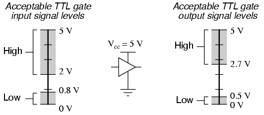 ) especially as there is 500ohm resistor between Atmega in the stove and data pin. I hoped you would get a diode ~0.6 or 0.8V Vf max. You can try it with this diode too. But in the board I made 2 days ago I used a higer voltage zener with Vf=0.9V as I don’t have a normal smd diode and I am suspecting that this is why it doesn’t work (measured around 0.9V on stove data line when TX is on 0V). Will solder a different diode today and let you know if that helped.
It’s always a bit of trial and error. Transistor should be fin, I am not sure about the diode though. Datasheet for your diode says Vf=1V. If it will be 1V difference in this schematic too it would mean when the CP2102 sets the TX line to 0V, it will be 1V after the diode on the stove’s side. And it may not be low enough to be registered as logic 1 by the stove (see
k3a
Used 1N5817 get the odd error but checksums Ok
k3a
on another note I think the Amega 328 (micronova board) is 5 Volt CMOS
http://www.allaboutcircuits.com/textbook/digital/chpt-3/logic-signal-voltage-levels/
@Gus
Yes, you’re right. Atmega is CMOS. In that case 1V forward drop diode should be fine too. My problem was in the software, not the diode. I managed to connect 3.3v (no 5v tolerant) ESP8266 by just adding one zener diode on TX side. I see some short, higher-voltage (~3.7V) spike on RX line after rising edge, this is probably related to the transistor, but does it mean it conducts in reverse (so current going from E to C for a short period)? http://postimg.org/image/jetcp11u5/ It works and it’s roughly in the voltage limit of this chip so I won’t probably try another transistor… I will update the blogpost soon and split it into two posts, so this one will be communication only, the other will be that LCD stuff as it’s not that useful generally.
k3a
Excellent ,I have the esp8266 as well with the 5Volt interface trying to use it as a transparent
bridge but no luck yet . So you are able to communicate with the Micronova board at 3.3V ?
Which 2Wire/1Wire interface are you using?
Not sure 100% but if I remember correctly the TXD and RXD pins on the AT328 are connected
together on the circuit board ,would be possible to cut the trace and bring out the TX and RX on a 2 Wire and avoid all this 1Wire problem
Regards
@Gus
Yes, I am using esp8266 to communicate with the stove. I’ve updated the blogpost with my latest schematic. See the image at 1/4th of the page. It’s the schematic you mentioned with just one zener on txd. I used 3.3v zener but 3.6 or so would be ok too. It works fine, no echo. I don’t know how they did it on the atmega side, never disassembled the stove to access the majn board, maybe they just used one gpio of that atmega, switching between output and input pin mode.
k3a
Shot in the dark, maybe the response time of your zener could give you the 3.7Volt overshoot
Later
Gus
PS
When you update the blog fell free to delete streamline all the non relevant info from my posts ,so the next guy does not need to read the B.S. (Bullshi#)
Sorry for asking stupid questions but I’m trying to figure it out :)
1. What is voltage of TxRx wire that coming from the stove in idle state? I grab 4 wires from main board serial connector (CN13), and I have GND, +15V, and two +5V wires. Don’t know which one is correct one.
[IMG]http://i65.tinypic.com/30adtep.jpg[/IMG]
2. If I use regular multimeter (not scope) can I see changing levels when pressing something on keyboard (when keyboard communicates with main board). I guess that these changes are with high frequency so multimer can’t display it but just asking.
3. I’ve got new diode, some schottky BAT43 and tried to build 1 wire-2 wire circuit without success. Using Serial Port Monitor for monitoring all traffic across serial port and it looks like I’m sending something but I don’t get anything from the stove. That’s the reason why I’m thinking that I don’t use correct wires…
Thanks
@Vladimir
None are stupid, that’s the way to learn. ;) I am also still learning.
1) It’s basically 5V. It’s pulled to 5V via a ~35k ohm resistor internally. This is the state of the line when idle or logic 1. On logic 0 it brings down the line near GND to make it lower then lowset voltage level for 5V CMOS. For more info on this topic https://learn.sparkfun.com/tutorials/logic-levels. Your problem may be in the GND. Voltages are always relative, you compare potential between one level and the other. Don’t use stove’s metallic enclosure as GND, while it is grounded to safety, it is not connected with logic GND and there is a few voltage difference. Try to take GND from the mainboard somewhere. If you figure out the CN13 pinout, please let us know, it may help others.
2) Yes, you are right. Multimeter updates only few times in a second, depending on the type, but usually something like 5 updates per second. Baud rate here is 1200 meaning 1200 changes can happen per second. One change is approximately one bit of data. Approximately because there are two stop bits after every byte. To debug these things you either use a scope or a logic analyser. There are some cheap chinese Saleae clones for $12 which work ok. The difference between this and the scope is that logic analyser often gives you logic values only (1 or 0) and can do the protocol analysis while the scope measures the actual voltages over time so you can see the exact voltage levels.
3) It’s difficult to say without seeing the traffic. But it’s quite possible your problem is wrong wires. Also ensure that you are setting 1200 baud rate with 2 stop bits, 8 data bits and no parity.
@k3a
1. Yes, you already wrote about difference between GND (logic reference) and safety earth so I used your photo (LCD/controller back) which shows which pins you used. I turned off the stove, and checked if some of my 4 wires (from serial connector) is short conected to some of yours pins on LCD/controller board.
http://i64.tinypic.com/2v3osoo.jpg
Marked pin on photo is direct connected to one of 4 pins on serial connector. I assumed that it is ground. A connected black contact of multimeter to that wire, and measure reamining 3 wires, and all voltages are positive, so I’m pretty sure that it is GND. I must figure out which of these remaining wires are power supply for Micronova “Serial interface” and which is TxRx. :)
3. Yes, at the beginning I configured COM port with that settings. Also, I tried to communicate with stove using SeramiNet, but although I installed english version of application, plenty of options are still in itallian so I don’t know what I can to click but to avoid making some problem. I selected com port, configure baud rate and everything else and at the bottom of the application seems like it’s connected but I don’t know how to test :)
Back to the laborotory :)
Thanks for help
@Vladimir
1. That gnd should be ok, yes. You can also measure the voltage on the lcd back to verify. I commented that back for you here http://postimg.org/image/a8jeval71/
3. You can use RealTerm for windows http://sourceforge.net/projects/realterm/ and set Display as Hex, configure the port and send two bytes 0x00 0x01, stove should respond with 2 bytes if it works. For SeramiNet, you select the port and click Open or something like that. Then the best way of testing it is opening EEPROM or RAM memory page. It will scan various addresses and read values. If it is reading 0xFF it doesn’t work. If it works you will see some numbers there.
Hope it helped.
@Vladimir
Oh and also if your multimeter can measure resistance you can turn the stove off and measure resistance between what is marked as IR pin and all the CN13 pins. There is ~500 ohm resistance between IR and RxTx, it’s almodt the same line. Higer resistance (kohms) means it’s not the pin you want.
@k3a
I think we made some progress :)
http://postimg.org/image/5hyki5ik9/
Many thanks again. I will experiment tomorrow so I will send report what I’ve done.
Looks like it works for you. This is what I meant by viewing memories. It automatically refreshes all parameters 0x00 – 0x7F. http://postimg.org/image/rekq4au8h/ I’ve been recording this screen on video and then watching parameters change during all common stove phases to get the params I needed. I found all params I need this way but of course someone can plot these variables in chart to better understand all of them. Maybe even seraminet can plot them somehow but I don’t know how. It seems they have some file with mapping which you would load into seraminet and it would define which parameter is located on which address. This doesn’t seem to be public so we have to find the addresses ourselves. You can use addresses I mentioned in the post, they may be the same for you, or at least some of them.
Yes, I opened that table, and you are right, it refreshes values every 2-3 seconds and I already recognized some values thanks to your instructions but, as you can see on screenshot, at the bottom of the application some communication error appears.
http://s23.postimg.org/8dn6gopff/RWMS_error.png
I guess this isn’t good?
@Vladimir
Hmm, it isn’t good. It sent 00 14 trying to read value at address 14 and received 15 02. It should have been 15 01 or 16 02. So maybe one bit was missed or added somewhere. Maybe a different transistor would work better, who knows, hard to say without a scope. :( Overall it appears to work though. So in reality it may be no big deal if sometimes some commamd fails. You can repeat. Depenig om your requirements.
What is the CN13 pinout btw please?
Hello, i find you have Great ideas..
My pelletstove is a extraflame bella
With a micronova motherboard..
The controlpanel is an Old LED and
If possibel i wana change it to the
Same like you use…
If i Start my stove, its showing
Programm 40
User
Time
I want to make an update, is it
Possibel over the DB9 ???
And dies it give an direkt adapter
From the stove DB9 to the PC rs232
To buy???
Best regards
Lui
@k3a
I will try with different transistor, who knows what is the problem. I was watching and analyzing and this error appears once in a 2-3 minutes. I hope it’s not big deal as you said. :)
Guy from italian forum who post “crazy schematics with optocaplers…” was right with his pinout of serial connector. :)
http://s23.postimg.org/pjjsonbfv/Konektor.png
This is pinout which I use
http://s11.postimg.org/xrqk32d5v/Konektor2.png
On second screenshot I marked two pins which are required for communication. Other two are probably for powering “official micronova serial interface”.
I tried to communicate with stove using third party applications (RealTerm, SerialPortMonitor, Putty…) but I don’t get any response from stove. I configured serial port (1200,N,8,2) and send commands as strings. Am I doing something wrong?
Can you send a few more examples of commands and what should be response from stove? Thanks
Make sure not use the port in another app. Then RealTerm requires reopening the port after changing connection params, make sure to press some button (don’t know the button name by heart). Then send commands as hex numbers (or other numbers but you are sending binary bytes not a string). So something like 0x00 0x01 would instruct the stove to read value at addresss 1 and will report something like 0x23 0x22. Checksum will be +1 because there is only 1 in the sum of the request bytes. You can configure RealTerm to display hexnumbers, maybe even decimal. This command is the simplest and you can change the second byte to read different addresses e.g. 0x00 0x0A to read byte at address 10 (0x0A in hex). In the blogpost there is also command to power on the stove by writing some value. I will also add command to change stove power setting. It works the same way just writes into a different memory. Is it working? If not I will make some screenshots but I am away from my house for a week.
@k3a
Hello,
I have to commend that with your help I managed to communicate with my stove. The point was sending HEX command while I’m obviously out of experience, kept sending commands in ASCII format that stove ignored.
I was successfully read some of the “mapped” values, and I was able to light the stove with command which is extra. What I planned is to try to figure out in which addresses are defined time of switching on and off in the chrono mode, as well as the parameters of the snail and fan. After that, I will try to write software for microcontroller (arduino) which would send the commands, and as a frontend would presumably used Blynk platform for Android, because I would say that it seems a lot easier for creating a functional interface rather than a web server and a responsive page …
I’m happy. Thanks so much for helping :) I will inform about my progress. :)
Very good you guys -35C at the moment I am not playing with stove :)
@Gus
Where are you from Gus? In Serbia is pretty hot for this time of year, average daily temperature is around +5C. Last year in december was a lot colder. Global warming I guess. :)
http://weather.gc.ca/city/pages/nt-4_metric_e.html driving to Yellowknife tomorrow in the AM
http://weather.gc.ca/city/pages/nt-24_metric_e.html not much better there
Hi, I’ve been following this thread for a while but the board I have seems a different model then all the ones I’ve seen mentioned.
Mine is a pellet boiler (not a stove), model is MCZ Logika and the board inside says N050.
It all seems it’s a Micronova one (the components used, the labels etc) but I’m not 100% sure.
The only reference which lead me to think it’s a Micronova is the wiring diagram of the boiler, where the serial connector is marked as “SERAMI”.
My need is quite basic indeed, I want to check whether the boiler is not in error status mainly. It happened a few times the pellet wasn’t loading properly from the external tank and the boiler went into protection mode. Of course it happened during the night and I realized that only when it was already freezing my ears off.
Well it would be great to control/set the temperature etc.
Do you think it would be just a matter of different EEPROM addresses/values?
thanks
It’s hard to say. You can see how Micronova boards look like in google images (https://www.google.cz/search?q=micronova+stufe+scheda&tbm=isch). If you see a 4 pin CN13 connector it may be it. You can use a multimeter and measure voltages on these pins relative to a GND on the board. If it is a Micronova board with a serial connector, it almost surely will be possible to control it the described way.
Hi,
i’ve got a stove which trademark is Superior.
It has got a DB9 connector backside.
I plugged in DB9 and communicated with it.
Code to start is okay, but I met problems to stop it.
When I send 0 to 0x21 (state), stove stops but without cleaning. It may be dangerous.
When I send 5 to 0x21 (state), stove may start cleaning indefinitely without stopping.
Does anyone know what procedure to apply to stop correctly the stove please ?
Thank you for your site and all your information.
Hi,
My pelletstove is a Superior.
I use its DB9 to send commands as described here.
I can switch on and off my stove ! :-)
But I met problems with stopping the stove.
Writing 0 to 0x21 stops the stove without cleaning.
Writing 5 to 0x21 starts cleaning but without stopping the stove… don’t know why…
Have you met such a problem ?
Could you please tell me the command sequence to write to 0x21 to stop correctly the stove ? Or explain why it is not as simple to stop it (do I have to launch cleaning during a while, then have to send the stop command by myself ?).
Thank you for your help.
Regards,
thank you for sharing all those informations.
@JLC
Sorry for the double Question, I did not see my previous question (thinking it had not been taken).
@JLC
In my case, when I write 0 to 0x21, my stove automatically switch to “cleaning final” mode (not instantly OFF). At first test I thought I have identical problem because after 10 minutes stove was still in “cleaning mode” but it turned out that it takes a little longer for stove to turn off when use command relative to using power button on LCD/controller.
Same as you, if I write 5 to 0x21, stove stay in cleaning mode permanently.
Commands I use for turning on and off:
Turning ON 80 21 01 A2
Turning OFF 80 21 00 A1
@Vladimir
Hi,
Thank you for your help.
I’ll try those commands.
I will come back to give my return.
Hi,
I’ve made some tests :
I switched on the stove by my self pushing its on button. Stove has worked for 3 hours.
I tried to stop it using some commands :
– First : I sent OFF command : 80 21 00 A1. Stove stopped, pellets stopped falling, but pellets that were in the brasero continued to burn. Cleaning procedure did not start.
– Then I sent cleaning command : 80 21 05 A6. Cleaning procedure started, and reading stove state returned 5 code. BUT, pellets restarted to fall and stove as well. Reading stove state returned then 4 code : stove is working… !
– Then I sent this cleaning command : 80 21 06 A7 (code 06). Cleaning procedure started without stopping itself. I’v been waiting for 30 minutes… then I stopped by my self sending OFF command.
I’ll try new tests.
@JLC
Maybe you are sending cleaning firepot instead of cleaning final? Can you watch states during a standard manual power off? Maybe your stove uses different codes.
I can’t figure out how to read error codes. That’s last thing I want to be able to read, before I start writing my arduino code.
http://s1.postimg.org/d6mfcqcdb/DSC_0382.jpg
In my instruction manual I have list of alarms so I assumed that last character (1-9, A, B) is reference of error code but after days of testing and simulating, I didn’t manage to find out on which memory locations is stored information about alarm. Maybe it’s not just value, maybe there is some math… Here is the list:
AL1 – Blackout
AL2 – Smoke probe
AL3 – Hot fumes
AL4 – Smoke ventilator broken
AL5 – No fire
AL6 – No pellet
AL7 – Thermostat 100 C
AL8 – Pressostat
AL9 – Water probe
ALA – Hot water
ALB – Water pression
What do you suggest?
@Vladimir
Hi,
have you searched both in RAM and EEPROM (EEPROM addresses are in 0x20) ?
Alarms need to be stored also in EEPROM to be displayed (at least known) when stove is restarted. May be your stove stores only alarm flags in EEPROM ?
@Vladimir
Maybe alarm flags are bit coded, for example :
– AL1 is bit 0 of BYTE X
– AL2 is bit 1 of BYTE X
– AL3 is bit 2 of BYTE X
– AL4 is bit 3 of BYTE X
– …
– AL9 is bit 0 of BYTE Y
– ALA is bit 1 of BYTE Y
– ALB is bit 2 of BYTE Y
In this case, only a few bytes would store alarm states.
@k3a
This morning I ran my stove by its ON OFF button, and let it work for a while.
Then I launched stop procedure by its ON OFF button. I read stove state : 6.
When stove had totally stopped, I started it again using ON Frame.
I read states till stove code was 4 (work).
Then I tried to stop it sending code 6 : 80 21 06 A7
Pellets stopped falling, cleaning procedure began…
But it is still running permanently… (I stopped procedure after 20 minutes).
Except 3 first states (0, 1, 2), it seems next states don’t relay each other by themselves…